 |
|||||
|
|
|||||
|
Practical Field Information about Telecommunication Technologies Vol. 8, No. 10, pp. 14–20, Oct. 2010. https://doi.org/10.53829/ntr201010pf1 Countermeasures to Lightning Backflow Current in Telecommunication CablesAbstractThis article describes countermeasures to the lightning backflow current induced in telecommunication cables by direct lightning strikes on various structures and facilities. It is the first in a new bimonthly series on the theme of practical field information about telecommunication technologies. This month’s contribution is from the EMC Engineering Group, Technical Assistance and Support Center, Maintenance and Service Operations Department, Network Business Headquarters.
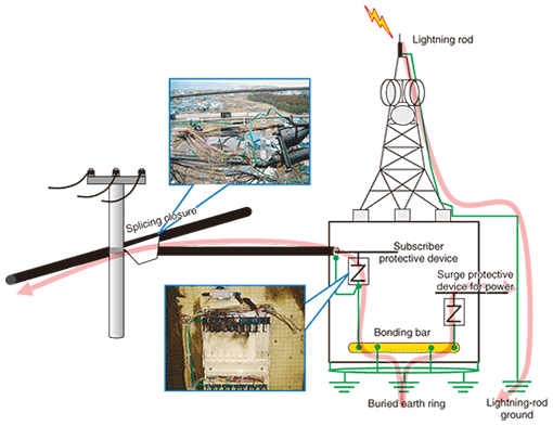
1. IntroductionSubscriber protective devices and telecommunication cables themselves can be damaged by direct lightning strikes on wind turbines, antenna towers, or other user facilities. In fact, the huge amount of energy generated by a direct lightning strike can cause extensive damage, and repairs to replace a long stretch of cable can be expensive and labor-intensive. This is a matter of considerable concern in the field. This article describes the factors that lead to faults in telecommunication cables as a result of the surge current (lightning backflow current) produced by direct lightning strikes on structures and facilities and outlines countermeasures to those factors. 2. Factors causing faultsA direct lightning strike on facilities like an antenna tower causes the ground potential of the user facilities to rise, which in turn causes a surge of current (lightning backflow current) to flow in telecommunication cables and power cables via the subscriber protective device (lightning arrester for telecommunications) and surge protective device for power (Fig. 1). Triode lightning arrester tubes used in subscriber protective devices can withstand a current surge in excess of 15kA (current waveform: 8/20 µs), but if there are only a few connected lines, current will flow in a concentrated manner, damaging the cable. In other words, faults will occur in the subscriber protective devices in facilities using a common ground and bypass arresters.
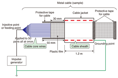
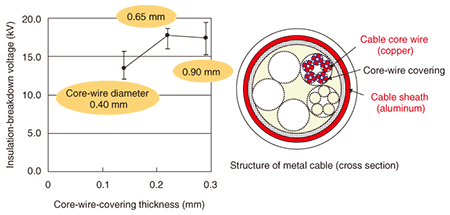
At the connecting point of a telecommunication cable, a potential difference will occur between a core wire* in which lightning surge current from user facilities flows and core wires or the cable sheath in which it does not. This situation can lead to an insulation breakdown, leading in turn to damage to the telecommunication cable (cables do not actually melt owing to lightning surge current). The voltage at which insulation between a core wire and the sheath breaks down depends on the core-wire diameter, and hence on the thickness of the core-wire covering. The dielectric strengths for core-wire diameters of 0.65 and 0.90 mm are greater than that for one of 0.40 mm. When actual dielectric strengths were measured using the system shown in Fig. 2, it was found that the insulation-breakdown voltage (voltage waveform: 1.2/50 µs) between core wires and cable sheath was about 14 kV for a small core-wire diameter of 0.40 mm and about 18 kV for ones of 0.65 and 0.90 mm (Fig. 3). In addition, to check whether such a potential difference occurs in actual telecommunication facilities, a simulated facilities environment was constructed and an experiment in which surge current was made to flow from user facilities through a single core wire was performed. It was found that a surge current of 200 A in the core wire generated a potential difference of at least 2 kV with respect to other core wires or the cable sheath at the connecting point. Now, assuming that the potential difference between core wires or between a core wire (with surge current passing through it) and the cable sheath is proportional to the surge current, simple calculations show that a surge current of about 1.4 kA or greater in a cable with a core-wire diameter of 0.4 mm generates a potential difference that exceeds the insulation-breakdown voltage described above, resulting in damage to the cable. The same holds true for a surge current of about 1.8 kA or greater in a cable with a core-wire diameter of 0.65 or 0.90 mm.
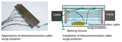
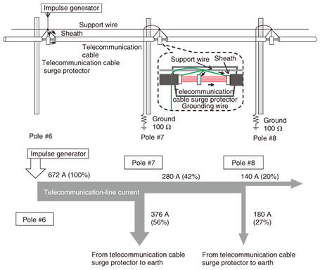
3. Basic ideas for countering direct lightning strikesApplying the following three ideas in combination is an effective means of protecting subscriber protective devices and telecommunication cables from direct lightning strikes on facilities. (1) Reduce the lightning backflow current. (2) Establish an equipotential state between core wires and between core wires and the cable sheath. (3) Improve the dielectric strength of core wires. Specific countermeasures at various locations in the system are described below. The numbers in parentheses correspond to the ideas listed above. 3.1 User cable terminator (main distribution frame etc.)When an antenna tower or other telecommunication facilities having a high probability of receiving direct lightning strikes is being erected, an effective means of providing protection is to increase the number of deployed cables, even if the number of user lines is small, and terminate all core wires at the subscriber protective device. These countermeasures can split the lightning backflow current and reduce the risk of exceeding the maximum tolerable surge current in the lightning arresters for telecommunications (1). The Technical Assistance and Support Center recommends cables with at least 30 pairs of core wires. Furthermore, for an equipment configuration in which a telecommunication cable for 30 user lines is deployed despite the fact that only a few (such as five or so) user lines are actually being used, if all the core wires are terminated, the current will flow through all of them, thereby eliminating potential differences that could lead to insulation breakdown (2). And to reduce the risks even further, the Center recommends cables with a core-wire diameter of 0.65 mm or greater because of their high dielectric strength (3). 3.2 Cable connector (splicing closure)A cable connector can also have a configuration in which potential differences arise between core wires or between core wires and the cable sheath owing to lightning backflow current. For example, locations where the number of cable core wires is reduced or where cable branching occurs may result in unconnected core wires or the cable connections that take different routes. If such connection equipment is located in the vicinity of an antenna tower, it is not uncommon for a large surge current flowing through the facilities to create a potential difference, resulting in insulation breakdown and cable damage. This damage may extend for even several kilometers, depending on the lightning’s magnitude. One countermeasure to this problem is to install a telecommunication cable surge protector (Fig. 4) to eliminate potential differences between core wires and between core wires and the cable sheath (2). In addition, the ground connection of the telecommunication cable surge protector serves to divert some of the surge current passing through the cable to earth, thereby reducing the amount of current flowing through the cable (1). In the experimental setup shown in Fig. 5, simulating an actual environment, it was found that surge current could be reduced by about 50%. Therefore, it can be said that a telecommunication cable surge protector need not be installed as far as the last point of damage that would be caused by a far-reaching, pre-countermeasure surge current. In summary, the installation of telecommunication cable surge protectors applies two of the three basic ideas for countering direct lightning strikes, namely (1) reducing the lightning backflow current and (2) establishing an equipotential state between core wires and between core wires and the cable sheath.
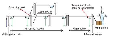
The following describes the effective installation of telecommunication cable surge protectors. To begin with, a telecommunication cable surge protector should be installed for the splicing closure on the cable-pull-in pole that draws in the cable to a user facility (user’s antenna tower, user’s wind-turbine, etc.) expected to receive direct lightning strikes. Another telecommunication cable surge protector should be installed at the first utility pole at least 100 m away from the cable-pull-in pole. Then, telecommunication cable surge protectors should be installed at two or more cable connection points every 500–1000 m as well as at branching poles used for branching a cable a relatively long distance (Fig. 6). In addition, locations where splicing closures have burned out in the past and areas where protector and terminal faults due to lightning have often been reported should be investigated as candidates for telecommunication cable surge protector installation. Installing a telecommunication cable surge protector at a pole where an underground cable emerges can also be effective.
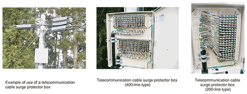
When a telecommunication cable surge protector is being installed, all core wires are connected regardless of whether they correspond to lines in use or lines not in use. Thus, at a cable branching point, the required number of wire pairs matches the side with the greater number of wire pairs, that is, the trunk-line side. However, if the trunk cable has many wire pairs and a telecommunication cable surge protector cannot be housed inside the splicing closure, then either multiple splicing closures will have to be installed or a telecommunication cable surge protector box will have to be used (Fig. 7). The ground line of a telecommunication cable surge protector connects both the cable sheath and support line to earth.
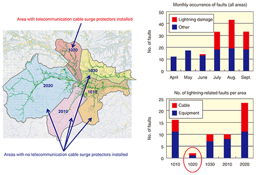
The ground connection of a telecommunication cable surge protector diverts the lightning backflow current passing through the cable, which means that a surge flowing in the reverse direction from that ground line must also be prevented. If a power line on a utility pole shared with a power company is also grounded, it is recommended that the ground for the telecommunication cable surge protector should be isolated from the power ground to the extent possible. 4. Effects of countermeasuresThe Technical Assistance and Support Center provides technical assistance related to protectors and cable damage caused by direct lightning strikes on antenna towers or other user facilities. The Center has proposed the countermeasures described above and has been instrumental in constructing many facilities where such damage has not reoccurred. The data shown in Fig. 8, while not associated with a telecommunication cable surge protector countermeasure specifically for direct lightning strikes, compares the states of faults between an area where telecommunication cable surge protectors are installed and areas where they are not.
Eliminating the potential difference between core wires and reducing the lightning backflow current by using a telecommunication cable surge protector also have the effect of reducing faults caused by induced lightning. The deterioration of insulation in telecommunication cables progresses steadily as a result of induced lightning (which has low energy), which means that the telecommunication cable surge protector can also be viewed as an effective means of extending cable life. 5. ConclusionThis article described the factors causing faults in telecommunication cables caused by direct lightning strikes on antenna towers or wind turbines and introduced countermeasures to them. Communication facilities that are used over the long term, like telecommunication cables, are subjected to repeated construction work (e.g., facility upgrading/expansion and obstacle removal). Consequently, even a thorough implementation of countermeasures when responding to lightning-related faults will not prevent the facility’s configuration from gradually deviating from the configuration intended to be achieved by those countermeasures or the reoccurrence of lightning-related faults from becoming likely. Checks on facilities should be performed as part of the operations to reduce the risk of lightning-related damage. |
|||||


