|
|||||||
|
|
|||||||
       |
Practical Field Information about Telecommunication Technologies Vol. 9, No. 8, pp. 103–107, Aug. 2011. https://doi.org/10.53829/ntr201108pf1 Corrosion Fractures in Wire GripsAbstractThis article describes corrosion fractures in wire grips and introduces countermeasures to this problem. It is the sixth in a bimonthly series on the theme of practical field information about telecommunication technologies. This month’s contribution is from the Materials Engineering Group, Technical Assistance and Support Center, Maintenance and Service Operation Department, Network Business Headquarters. 
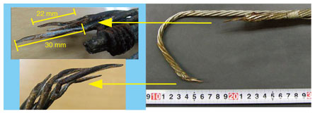
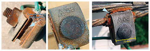
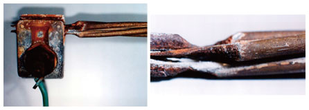
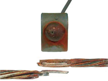
1. IntroductionUtility poles, messenger wires, and other facilities that support telecommunication cables over an aerial span progressively deteriorate over time owing to exposure to the natural environment. However, their reliability can be improved by using designs that provide a large safety margin and by selecting products that are more suitable for the target environment. Nevertheless, there are situations in which damage can still occur because of various external factors, such as fatigue-induced fractures in areas that experience strong winds, saline damage in coastal areas, and damage caused by sulfur in hot-spring regions. Another factor in the electrolytic corrosion of metallic materials is stray current from railway lines. While it is known that electrolytic corrosion can occur in lead-covered cables or lead conduits, it can also cause problems in aerial facilities via ground lines. The wire grip that terminates a messenger wire is equipped with a ground clamp, and the flow of ground current in the ground line can cause electrolytic corrosion to occur in the wire grip and ground clamp. This article reports on corrosion-related fractures that occurred where ground clamps were attached to wire grips and messenger wires. 2. Wire gripA wire grip is a fastener for attaching a messenger wire or guy wire to a utility pole. It can be applied quickly by simply twisting it around the messenger or guy wire manually and its gripping force remains constant over the long term. It is thus an important component that plays the role of terminating a messenger wire supporting a telecommunication cable or a guy wire maintaining a weight balance. The fracturing of a wire grip can consequently lead to a major accident. To prevent such accidents from occurring, wire grips must be appropriately maintained. 3. Case study: fracture in aluminium corrosion-resistant wire grip3.1 Facility configurationThis case study concerns an accident in which an overhead telecommunication cable fell to the ground because of a fracture in the aluminium corrosion-resistant wire grip where the ground clamp was attached. The facilities involved in this accident consisted of an aluminium corrosion-resistant wire grip (cross-sectional area: 30 mm2) used with a No. 1 thimble, a 30AW messenger wire (consisting of 30-mm2 aluminium corrosion-resistant strands) terminated by the wire grip, and a 0.4-30CA telecommunication cable (deployed in 1985) supported by the messenger wire. The wire grip and messenger wire were assumed to have been installed in 1985, the same year as the telecommunication cable, while the ground clamp was known to have been installed in 1988. The cable pathway ran alongside a roadway and parallel to a railway in a coastal area having many factories. The section of cable where the corrosion-related accident occurred was located about 600 m from the coast. 3.2 Observation of samplesWhen the fractured wire grip and ground clamp were examined, it was found that the portion of the ground clamp in contact with the wire grip was heavily corroded. Moreover, the wire grip was severely wasted away in a region 20–30 mm from the fracture point (Fig. 1) indicating that the corrosion had progressed locally. Since a maximum wastage of 1.03 mm occurred in a strand with a diameter of 2.60 mm over a 21-year period from 1988, the corrosion rate was 49 µm per year. The normal corrosion rate of aluminium is 0.4–0.6 µm/year even in coastal areas [1], and since the standard thickness of the aluminium covering in the aluminium corrosion-resistant wire grip is 180 µm, a corrosion rate of 49 µm/year is extremely high. When the ground clamp was examined, red rust could be observed in the bolt section and main body. Moreover, in the section of the ground clamp in contact with the wire grip, some of the strands of the wire grip were found to have fused with the ground clamp (Fig. 2). Corrosion had also occurred on the wire grip on the other side of the utility pole at the point where the ground clamp was attached. The above facility configuration and the sample observation results made electrolytic corrosion at the ground clamp a prime suspect. To check whether current had been flowing through the messenger wire or wire grip, NTT EAST personnel conducted a survey in the field.
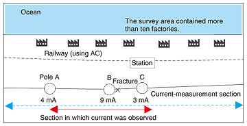
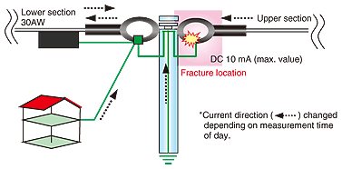
3.3 Survey details and resultsThe survey covered a range of about 4 km from the point of the fracture accident. A digital clamp meter was used to measure current (AC and DC) in messenger wires, wire grips, and ground lines, and a multitester was used to measure resistance between a ground clamp and messenger wire, between a ground clamp and wire grip, etc. For each utility pole, the complete set of measurements was performed twice―first in the morning and once again in the evening―to see whether the values depended on the time of day. At the time of the survey, the fractured wire grip and corroded wire grip had already been repaired. Measurement results are shown in Figs. 3 and 4. No AC was observed at any location, but DC was observed in the section from utility pole A to utility pole C (about 2 km). At the fracture accident location, a DC value of 9 mA was measured at 10:00 AM and 10 mA was measured at 4:00 PM. The direction of current flow changed for the two measurement times at the same measurement location. Furthermore, in the surveyed range, no corrosion was observed in messenger wires, wire grips, or metallic components even in those segments in which DC was measured.
3.4 Inferred cause of fractureThe results of measuring current and resistance and making observations suggest that current was flowing through the point of contact between the wire grip and ground clamp under investigation here, which caused electrolytic corrosion to occur and progress and this caused the messenger wire to fracture. The occurrence of a potential difference due to the effects of stray current can generate a current loop along the path: earth, ground rod, messenger wire, ground rod, and earth. If the ground clamp, messenger wire, and wire grip are insulated and if their surfaces get wet (from rain or other sources), current flows through this film of water, creating the possibility of electrolytic corrosion in the messenger wire and wire grip. Since the contact resistance between a ground clamp and wire grip is high, we inferred that current did indeed flow through a water film, which resulted in the generation of electrolytic corrosion. Rainwater can easily collect between a ground clamp and wire grip, and since the fracture point was located only about 600 m from the coastline, it is possible that rainwater containing particles of sea salt promoted the electrolytic reaction. Although a railway is frequently the source of current in messenger wires and similar facilities, it was found that the nearby railway in this case used AC, and since no AC was be detected in this survey, it was concluded that the railway was not the source of current. There were also many factories in the area, but as the direction of observed DC changed according to time, it was difficult to estimate the gradient of the potential difference. In addition, the locations where current was observed extended across a wide range, which prevented the current source from being isolated. However, as the highest current value was observed at the fracture accident location, it was inferred that this location was situated in an environment in which electrolytic corrosion could easily occur. 3.5 CountermeasuresThe most effective countermeasure here would have been to deal appropriately with the source generating the current, but since the source could not be isolated in this survey, countermeasures on the facility side had to be taken and countermeasures will continue to be needed in the future. If the contact resistance between a ground clamp and wire grip is sufficiently small, a potential difference does not arise and electrolytic corrosion generation can be prevented. In the survey, the resistance between ground clamp and wire grip was measured* in many locations and a measurement reading of 0 Ω was obtained in all cases. It was therefore concluded that electrolytic corrosion would not be a problem even in areas where DC was observed. However, older-type ground clamps are zinc coated to prevent corrosion of the iron materials, but if that zinc plating disappears, the aluminium portion of the aluminium corrosion-resistant wire grip can come into contact with iron, generating bimetallic corrosion. Furthermore, as the resistance at such a corrosion location is high, the corrosion will be further accelerated by electrolysis whenever DC flows. Thus, in the section between utility poles A and C where current was observed, special attention must be paid to locations with the older-type ground clamps in future facility inspections. By contrast, the latest ground clamps are manufactured by zinc alloy die-casting, which means that bimetallic corrosion will not be a problem as long as aluminium corrosion-resistant wire grips are used. In other words, replacing the older-type ground clamps with new ones could also be an effective countermeasure. Furthermore, if a ground clamp is to be installed in existing facilities and the installation point is soiled or corroded, contact resistance will be high, which will make it easy for electrolytic corrosion to occur when current is flowing. Contact resistance will also be high if the ground clamp itself is soiled. Therefore, old parts should not be used and the contact area should be cleaned thoroughly before a new ground clamp is installed. Likewise, continuity checks between the wire grip and ground and between the messenger wire and ground should be performed.
4. Related case studies on corrosion4.1 Fracture of aluminium corrosion-resistant messenger wireElectrolytic corrosion can occur in messenger wires in the same way as in wire grips. This section presents a case study of a corrosion-related fracture at the location where a ground clamp was attached to an aluminium corrosion-resistant (AW) messenger wire. The accident occurred about 1500 m from the ocean in a river delta in a residential area dotted with small iron works and other small factories. The fractured wire was of the 30AW type deployed in 1980. The corrosion in this fractured wire is shown in Fig. 5. A sudden wasting away of messenger wire not seen in crevice-type corrosion was observed at the boundary between the corroded and normal parts of the messenger wire. It was therefore inferred that current was flowing in this boundary region causing electrolytic corrosion to occur.
4.2 Fracture of steel-wire messenger wireThe same kind of attention must also be paid to zinc-coated steel-wire (SW) messenger wire. When the contact resistance between the messenger wire and ground clamp is high and a potential difference exists, the formation of a water film having ionic conductivity will result in the flow of current and the occurrence of an electrolytic reaction. Once the messenger wire begins to act as an anode, its wire strands can erode as a result of an electrochemical reaction. Furthermore, in coastal areas, sea-salt particles can penetrate the water film, which makes it easy for an ionic conductive water film to form. An example of electrolytic corrosion in an SW messenger wire is shown in Fig. 6. The countermeasures described above can also be effective when attaching ground clamps to SW messenger wire. Moreover, since surface resistance is high in the phase preceding the appearance of red rust on the messenger wire; that is, when the zinc coating corrodes and white rust begins to appear, this white rust must be removed. The SW messenger wire is more susceptible to corrosion than AW messenger wire, so special attention must be paid when ground clamps are attached to existing SW messenger wires.
5. ConclusionThis article presented case studies of fractures in wire grips and messenger wires and described countermeasures to this problem. Although unexpected failures are bound to occur in facilities exposed to the natural environment, if appropriate measures are taken beforehand, the occurrence of fracture accidents can be minimized. The NTT EAST Technical Assistance & Support Center is working to clarify the causes of abnormal failures and to establish measures to combat them with the aim of improving the reliability of telecommunication facilities. Reference
|
||||||