|
|||||||
|
|
|||||||
       |
Feature Articles on Technical Solutions to Real-world Problems Vol. 10, No. 7, pp. 6–9, July 2012. https://doi.org/10.53829/ntr201207fa1 IEEE802.11n Wireless Local Area Network Troubleshooting Tool with Electromagnetic-environment Monitoring FunctionAbstractNTT EAST Technical Assistance and Support Center has developed a wireless local area network (WLAN) troubleshooting tool equipped with an electromagnetic-environment monitoring function that can visualize the signal strength and electromagnetic interference conditions of IEEE802.11n WLANs.
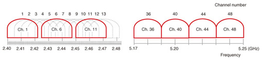
1. IntroductionEach revision of the IEEE802.11 wireless local area network (WLAN) standard has provided ex- panded functions in addition to higher communication speeds. It is implemented not only in personal computers but also in smartphones and other types of personal digital assistants. A tool for visualizing problems with IEEE802.11a/b/g WLANs has already been reported [1]. With the growing demand for higher WLAN speeds in both office and home environments, IEEE802.11n has become mainstream owing to its use of multiple-input and multiple-output (MIMO) technology and higher speeds achieved by expanding the channel bandwidth. The home gateway supporting the HIKARI DENWA function of the FLET’S HIKARI optical IP telephony service provided by NTT EAST and NTT WEST also supports IEEE802.11n (IP: Internet protocol). IEEE802.11n achieves high speeds by using MIMO spatial multiplexing technology and by expanding the channel bandwidth by utilizing the 2.4-GHz and 5-GHz bands. The 2.4-GHz frequency band, which is also called the industrial, scientific and medical (ISM) band, is used for communication systems such as Bluetooth and ISM equipment such as microwave ovens and microwave medical treatment devices. Electromagnetic waves emitted from such communication systems and ISM equipment have the potential to affect WLAN communications using the 2.4-GHz band. Therefore, a channel free from electromagnetic interference should be selected so that the high-speed performance of an IEEE802.11n WLAN can be used to the maximum. Furthermore, in addition to 20-MHz-bandwidth communications, the same as in the IEEE802.11a/b/g standard, IEEE802.11n supports 40-MHz-bandwidth high-speed communications by bundling two 20-MHz IEEE802.11a/b/g channels. However, 40-MHz-bandwidth communications—especially in the 2.4-GHz band—can easily encounter interference from electromagnetic waves emitted by other communication systems or ISM equipment as well as interference from IEEE802.11b/g WLAN signals on adjacent channels. Against this background, NTT EAST Technical Assistance and Support Center developed an IEEE802.11n WLAN troubleshooting tool in fiscal year 2010. This tool is equipped with an electromagnetic-environment monitoring function for visualizing IEEE802.11n WLAN signal strength and electromagnetic interference conditions. This article describes the IEEE802.11n channel configuration and the electromagnetic-environment monitoring function of this WLAN troubleshooting tool. 2. IEEE802.11n channel configurationThe channels allocated to IEEE802.11n WLANs consist of 13 channels in the 2.4-GHz band and 19 channels in the 5-GHz band. Each channel has a bandwidth of 20 MHz (strictly speaking, 22 MHz in the 2.4-GHz band). As shown in Fig. 1, the configuration of the 2.4-GHz band differs from that of the 5-GHz band in that adjacent channels overlap at 5-MHz intervals in the former while channels are independent of each other at 20-MHz intervals in the latter. Thus, when the 2.4-GHz band is used, the channels being used should be separated by at least five channels, as in channels 1, 6, and 11. Failure to do so could result in inter-channel interference.
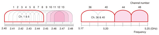
Furthermore, interference can also occur as a result of IEEE802.11n 40-MHz-bandwidth high-speed communications using two bundled 20-MHz-bandwidth channels. For example, when channels 1 and 6 are bundled, interference can occur from 20-MHz-bandwidth communications using channels 1–10 (no interference occurs with channels 11–13), as shown in Fig. 2. Similarly, when the 5-GHz band is used and channels 36 and 40 are bundled, interference can occur from 20-MHz-bandwidth communications using either channel 36 or 40.
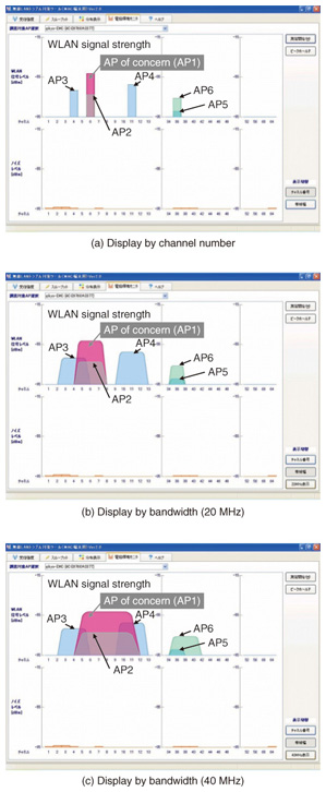
Therefore, to make best use of the performance available with IEEE802.11n, there is a need to understand three types of interference conditions and to set channels accordingly to prevent such interference from occurring as much as possible. To begin with, just as in the case with IEEE802.11a/b/g, measures must be taken against (1) same-channel interference caused by signals from another WLAN system using the same channel and (2) adjacent-channel interference caused by signals from another WLAN system using adjacent, overlapping channels. In addition, measures must also be taken against (3) channel interference unique to 40-MHz-bandwidth high-speed communications caused by signals from 20-MHz-bandwidth WLAN signals. Incidentally, the maximum transmission speed in 40-MHz-bandwidth communications is 300 Mbit/s, but that could drop to 144.4 Mbit/s because the occurrence of this third type of channel interference would lead to a reversion to 20-MHz-bandwidth communications. 3. IEEE802.11n electromagnetic-environment monitoring functionThis section describes the electromagnetic-environment monitoring function incorporated into the WLAN troubleshooting tool. The purpose of this function is to visualize the state of interference of the abovementioned three types. This section presents some results of monitoring conditions in an environment containing six WLAN access points (Fig. 3).
The electromagnetic-environment monitoring function can display results by channel number or by bandwidth (Fig. 4). As shown in Fig. 4(a), the channel-number display mode shows the signal strength of access points AP1–AP6 for each channel. Here, the access point signal strengths are shown in a stacked manner if more than one access point is using the same channel. These results reveal that AP1 is receiving same-channel interference from AP2.
By contrast, the bandwidth-display mode shows WLAN signal strength according to bandwidth. Figure 4(b) shows the results of monitoring conditions for 20-MHz-bandwidth communications. This display mode can visualize adjacent-channel interference and shows, specifically, that AP1 signals are being affected by those of nearby access point AP3. Figure 4(c), on the other hand, shows the results of monitoring conditions for 40-MHz-bandwidth high-speed communications. AP1 signals are being affected by AP4 signals using channel 11. 4. ConclusionThe WLAN troubleshooting tool presented here makes it easy to determine the presence of interference that can affect WLAN signals, including those of the IEEE802.11n standard. This tool is expected to shorten the time taken to troubleshoot WLAN problems. Reference
|
||||||