 |
|||
|
|
|||
|
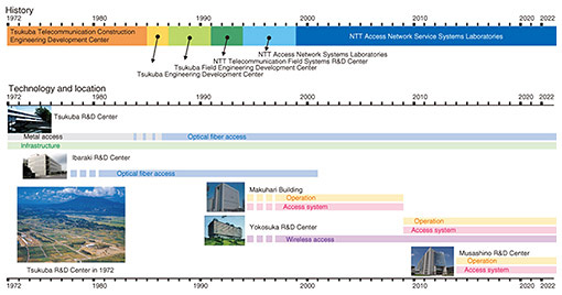
Feature Articles: Access Network Technologies for IOWN Vol. 20, No. 9, pp. 40–46, Sept. 2022. https://doi.org/10.53829/ntr202209fa5 50 Years at Tsukuba R&D CenterAbstractNTT Access Network Service Systems Laboratories was established in Tsukuba City on July 20, 1972 as Tsukuba Telecommunication Construction Engineering Development Center. Since then, it has been renamed several times during the era of the Nippon Telegraph and Telephone Public Corporation and the Nippon Telegraph and Telephone Corporation (NTT). In July 2022, the Laboratories’ Tsukuba Research and Development (R&D) Center celebrated its 50th anniversary. This article introduces the 50-year history of the Tsukuba R&D Center, focusing on the large-scale experimental facilities that supported R&D activities in Tsukuba. Keywords: access network, infrastructure, optical fiber 1. IntroductionTsukuba Telecommunication Construction Engineering Development Center of the Nippon Telegraph and Telephone Public Corporation, the predecessor of NTT Access Network Service Systems Laboratories, was established in July 1972 as a member of the 43 research and educational institutions planned for the Tsukuba Science City, a national project promoted by Cabinet approval in September 1963 [1]. As shown in Fig. 1, Tsukuba Telecommunication Construction Engineering Development Center was reorganized into Tsukuba Engineering Development Center (1985), Tsukuba Field Engineering Development Center (1987), NTT Telecommunication Field Systems Research and Development (R&D) Center (1991), and NTT Access Network Systems Laboratories (1994) and took its current name of NTT Access Network Service Systems Laboratories in January 1999. The Tsukuba R&D Center was established as the organization’s experimental facilities in 1972, and the Makuhari Building and Yokosuka R&D Center were added to the organization in 1997, and the Musashino R&D Center was added in 2014. In July 2022, NTT Access Network Service Systems Laboratories and its Tsukuba R&D Center celebrated their 50th anniversary.
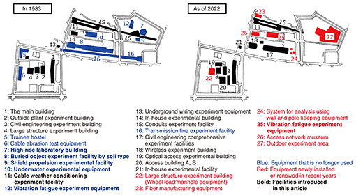
When it was first established as Tsukuba Telecommunication Construction Engineering Development Center, R&D activities on metal access technology and infrastructure technology were conducted in Tsukuba to improve the efficiency, safety, and work environment of outdoor construction work due to the increase in telephone service demand at that time. NTT Access Network Service Systems Laboratories is currently conducting R&D in the five fields of optical-fiber access technology, infrastructure technology, access system technology, wireless access technology, and operation technology. At the Tsukuba R&D Center, our R&D has been focused on communication lines and civil engineering facilities since the establishment of Tsukuba Telecommunication Construction Engineering Development Center. The Tsukuba R&D Center was designed to conduct various experiments under conditions equivalent to those in the field to create communication facilities that can work in various environments. Therefore, it has large-scale and unique experimental equipment and facilities for communication lines and civil engineering facilities. This article describes the large-scale experimental equipment and facilities that support the R&D in Tsukuba. 2. Large-scale experimental equipment and facilities at Tsukuba R&D CenterThe Tsukuba R&D Center has mainly been carrying out R&D on infrastructure technology, metal access technology, and optical-fiber access technology. This article focuses on the facilities that were constructed during the Tsukuba Telecommunication Construction Engineering Development Center era but have now completed their intended purposes. Figure 2 shows the facilities of the Tsukuba R&D Center in 1983 and the current ones on the vast site of about 22 hectares. Many of the facilities were designed to accurately reproduce installation environments such as the high-rise laboratory building (a vertical wiring experiment facility and was the highest in the world), buried object experiment facility by soil type, shield propulsion experimental facility, underwater experimental equipment, cable weather conditioning experiment facility, and vibration fatigue experiment equipment.
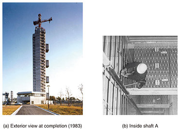
Figure 3 shows photographs of the high-rise laboratory building at the time of its completion (1983). With the increase in high-rise buildings, such as skyscrapers and large bridges, it was constructed for the purpose of improving vertical cable-laying methods and elucidating temperature changes in high-rise facilities and seismic behavior of high-rise facilities during earthquakes. Inside the building, there was a 75-m-high, 1.8-m-long, and 2.5-m-wide shaft (A) (from the 3rd story below ground to 12th story above ground) for cable laying experiments, static load tests, and vibration tests, and a 60-m-high, 1.0-m-long, and 1.0-m-wide shaft (B) (from the 1st story above ground to 12th story above ground) for vertical cable heat cycle tests (–40 to +80°C). It was used to verify the vertical installation of various cables. Today, vertically optical wiring installations are common in high-rise buildings, and their reliability is widely recognized and unshakable. The purpose of this experimental facility was accomplished, thus it was dismantled.
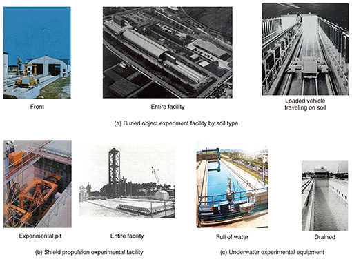
Figure 4 shows the large-scale experimental facilities used for verification of underground facilities and underwater communication lines and civil engineering facilities. Figure 4(a) shows photographs of the buried object experiment facility by soil type at the time of completion (1977). This facility was constructed to replicate installation under roads for the purpose of examining issues such as design, construction, and maintenance, because ground properties are diverse and difficult to predict accurately. The facility made it possible to alter soil quality, groundwater level, etc., and run a load car reproducing automobile loads over it. It was useful in various verification tests, such as the investigation of the effect of burying a full-scale manhole, and the investigation of the movement of optical fiber cable in the pipeline by burying a pipeline in the soil layer close to the actual site and driving a load car over it. Underground facilities for communication services have been installed all over Japan, thus this facility completed its intended purpose.
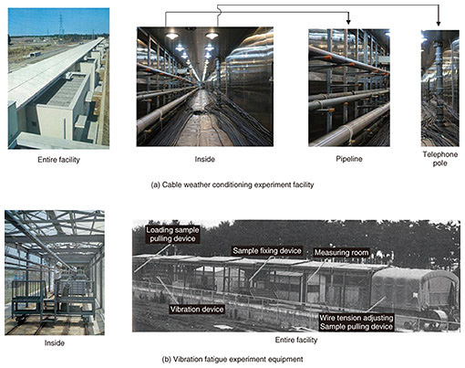
Figure 4(b) shows the test pit and panoramic view of the shield propulsion experimental facility. To apply the shield-tunneling method developed for road construction without using open pit methods, this facility was constructed to verify the adaptability and safety of the method, considering various construction conditions expected at different sites. By putting a sample of the soil layer under test into the pressure soil tank and using a water-pressure generator to apply arbitrary water pressures to the layer, predetermined ground conditions could be created. Therefore, a small model shield machine installed in the experimental pit was propelled into the soil layer, and experiments on excavation, soil removal, etc. were conducted. As the shield-tunneling method for various types of ground has become widely used, and the construction of new roads has been reduced, the shield propulsion experimental facility was dismantled upon completion of its purpose. Figure 4(c) shows an exterior view of the underwater experimental equipment at the time of completion (1974). It was constructed to test the laying of submarine cables and water-resistance tests of underground structures. It consisted of a water tank 50 m long, 6 m wide, and 5 m deep, underwater observation tunnel, moving bridge, bridge crane, and measurement room. The mobile bridge was self-propelled with a running speed of 10–50 m/min and used as a simulated submarine-cable laying device for conducting simulation experiments on submarine cables. Test methods for submarine cables and underground facilities were established, therefore this equipment has been removed. Figure 5 shows the large-scale experimental facilities used for the verification of aerial communication cables and civil engineering facilities in the open. Figure 5(a) shows the cable weather conditioning experiment facility at the time of completion (1973). Since most communication lines and civil engineering facilities are installed outdoors, this facility was constructed to reproduce actual cable installation environments and conduct weatherability tests and temperature-characteristic tests. Having a totally stainless steel roof and being 150 m long, 2.45 m wide, and 2.25 m high, it made it possible to reproduce in a test room the state of installation in a conduit, pipeline, and on a telephone pole. At the time of construction, the temperature could be changed from –20 to +60°C, but now it can be changed from –30 to +70°C. In optical cables, small bends in the cable affect various transmission characteristics, so we will continue to use the facility through various tests for the practical application of new fiber and cable structures.
Figure 5(b) shows the vibration fatigue experiment equipment when it was completed (1977). It was constructed for the purpose of clarifying the response characteristics, such as the increase in optical loss and fracture of cables, passive optical components, closures, and hardware, used in overhead lines by the imposition of vibration to replicate the effect of wind on aerial cables, etc. By providing feedback to the design, development, and verification of new cables and components, we have been able to enable safe long-term use of overhead equipment and facilities. This equipment can forcibly excite cables and suspended wires with actually installed aerial cables. At the time of completion, the maximum installation length was 35 m, but the maximum installation length has been extended to 65 m, and it will continue to be used for various experiments. As of 2022, we also have large-scale experimental facilities intended to support the Innovative Optical and Wireless Network (IOWN) and smart facilities, as shown in red in Fig. 2. 3. SummaryThis article introduced the R&D history of the Tsukuba R&D Center over the last 50 years, focusing on the large experimental equipment and facilities created to support the R&D of communication lines and civil engineering facilities. We will continue to conduct R&D activities toward the development of smart facilities that support IOWN, with the aim of achieving technologies that can be used to support both the most advanced in the world and easy-to-use in the field. Reference
|
|||


