|
|||||||||
|
|
|||||||||
       |
Practical Field Information about Telecommunication Technologies Vol. 21, No. 6, pp. 70–76, June 2023. https://doi.org/10.53829/ntr202306pf1 Deterioration of Telecommunication Equipment and Facilities in Salt-damage Environments—Case Studies of Corrosion in Guy Wires and Maintenance HolesAbstractThis article presents examples of equipment and facility deterioration due to corrosion of guy wires and maintenance holes installed in coastal areas as well as examples of countermeasures to protect equipment and facilities from salt damage. This is the seventy-sixth article in a series on telecommunication technologies. Keywords: salt damage, corrosion, maintenance hole
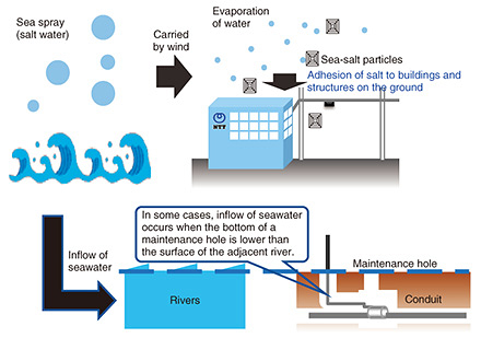
1. IntroductionNTT’s telecommunication equipment and facilities are installed throughout Japan in a variety of natural environments. Metals, concrete, and plastics are used as materials for telecommunication equipment and facilities, which deteriorate over time due to the effects of the surrounding environment such as ultraviolet rays, rainwater, and seawater. In response to requests from the field, the Technical Assistance and Support Center (TASC) has been investigating the causes of telecommunication failure due to salt damage in outdoor facilities and indoor equipment. Examples of equipment deterioration due to corrosion of guy wires and maintenance holes installed in coastal areas as well as examples of countermeasures to protect equipment and facilities from salt damage are presented in this article. 2. Factors causing salt damageAs shown in Fig. 1, salt damage, which is one of the causes of deterioration of materials, is a phenomenon by which particles of sea salt are blown into the air by strong winds and adhere to equipment containing metal, and the adhered salt accelerates the corrosion of that metal. Corrosion reactions caused by salt damage are accelerated by electrolytes containing salt, which increase electrical conductivity and facilitate the flow of the corrosion current. Since salt is hygroscopic, it absorbs moisture from the atmosphere and becomes wet, which increases risk of equipment corrosion. Since Japan has a long coastline, salt damage is an unavoidable phenomenon. Sea-salt particles originating from sea spray fall in coastal regions due to the limited distance they can travel, so the effects of salt damage are more pronounced on equipment closer to the shoreline, thus prematurely deteriorating the equipment.
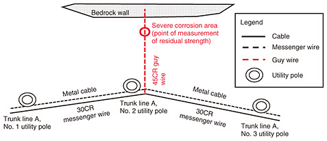
3. Cases of equipment and facility deterioration due to salt damage3.1 Corrosion of a guy wire due to salt damageFirst, we present a case study of guy wire deterioration along the coastline. The middle part of a guy wire of a utility pole had significant corrosion. The guy wire is installed about 30 m from the sea, and the region is designated as a high-salt-damage area on a “salt-damage map” developed and provided by TASC [1, 2]. The configuration of the facility in this corrosion case is shown in Fig. 2.
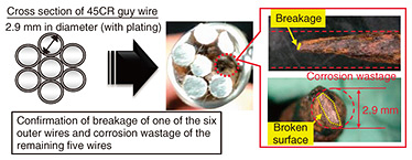
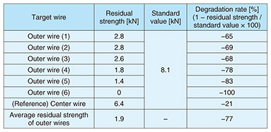
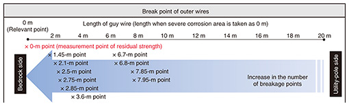
3.1.1 Investigation methodWe investigated the guy wire recovered from the site from two perspectives: (i) residual strength of the severe corrosion area and (ii) progress of corrosion in areas other than the severe corrosion area. 3.1.2 Results of investigationThe cross section of the severe corrosion area of the guy wire is shown in Fig. 3. We measured the residual strength of the wires within the guy wire. As listed in Table 1, the residual strength of the wires had decreased by an average of 77%. The progression of corrosion in areas other than the severe corrosion area is shown in Fig. 4, which shows the number of partially broken outer wires (“×” in the figure) increases from the utility-pole side to the bedrock side. This confirms that corrosion areas are more prevalent on the bedrock side than on the utility-pole side.
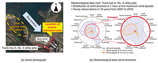
3.1.3 Estimation of the cause of corrosion and countermeasuresThe reason that the guy wire had severe corrosion on the bedrock side but light corrosion on the utility-pole side was estimated as follows and illustrated in Fig. 5(a). On the bedrock side, there are no obstacles blocking the air containing sea-salt particles above the sea from being carried by the sea breeze to the severe corrosion area of the guy wire. In other words, sea-salt particles in the air above the sea are blown in as they are. On the utility-pole side, however, the hill acts as an obstacle blocking the sea breeze and captures sea-salt particles blown in by the sea breeze. It can therefore be concluded that the difference in the corrosion state in those two sides of the guy wire is due to the difference in the amounts of sea-salt particles in the air blowing on those sides. This estimation is supported by the meteorological data (wind direction) shown in Fig. 5(b), that is, the hill on the upwind side of location A is located in a position where it obstructs sea breeze from the most-frequent wind direction (northwest).
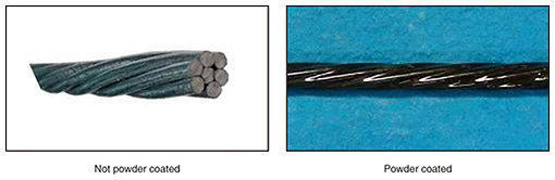
For a countermeasure against salt damage, it is first necessary to identify areas where corrosion progresses rapidly and requires careful inspection by referencing salt-damage maps, etc. Second, when conducting inspections, it is necessary to ensure that the entire facility is thoroughly inspected since the corrosion rate may vary—even for the same facility—owing to differences in environmental conditions such as wind exposure, which makes it possible to reliably detect unsafe equipment. When messenger wires and guy wires are renewed, implementing corrosion countermeasures such as replacement with products with stronger anti-corrosion treatment (e.g., powder coating [3]), as shown in Fig. 6, can be expected to extend the service life of equipment.
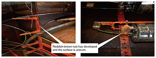
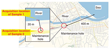
3.2 Metal corrosion in a maintenance hole due to salt damageCases of metal corrosion in a maintenance hole in a section located along a river are shown in Fig. 7. As shown in Fig. 8, the maintenance hole is located about 20 m from the river and about 400 m from the sea. It was previously confirmed that the bottom of the maintenance hole is 0 m above sea level or lower and that the water level inside the maintenance hole rises and falls due to the ebb and flow of the tide, so it was suspected that river water flows into the maintenance hole.
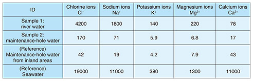
3.2.1 Investigation methodWater retained in the maintenance hole, corrosion fixtures, and river water were collected. Ion concentrations of the maintenance-hole water and river water were first analyzed by ion chromatography. The presence or absence of river-water inflow and the cause of corrosion were then analyzed by conducting X-ray structural analysis of the fixtures from the maintenance hole: mounting hardware with loose rust removed, a metal fixture with significant loose rust (metal-fixture adhering substance 1), and metal fixture with minor loose rust (metal-fixture adhering substance 2). 3.2.2 Results of investigationRegarding the analysis of ion concentration contained in maintenance-hole water and river water, as shown in the “Sample 1: river water” row in Table 2, high concentrations of chlorine and sodium ions were found in the river water. As shown in the “Sample 2: maintenance-hole water” row of the same table, the maintenance-hole water has higher concentrations of chloride and sodium ions than the maintenance-hole water from inland areas, which suggests inflow of river water into the maintenance hole.
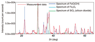
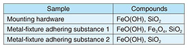
The results of the X-ray structural analysis of the mounting hardware and metal-fixture adhering substances are shown in Fig. 9. They indicate that metal-fixture adhering substance 1 contains iron-corrosion products, indicated by peaks at the spectral positions of hydroxides (goethite: FeO(OH) and magnetite: Fe3O4), which are formed when iron corrodes. As shown in Table 3, the other samples (the mounting hardware and metal-fixture adhering substance 2) were confirmed to contain a hydroxide, FeO(OH), which is an iron-corrosion product. Since iron corrosion is accelerated as the concentration of chloride ions increases and FeO(OH) generates Fe3O4, the above results suggest the effect of salt damage.
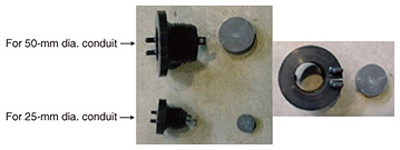
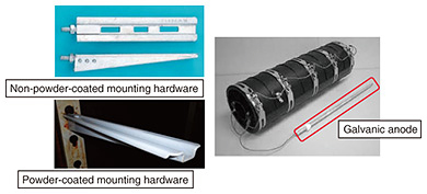
3.2.3 Estimation of the cause of corrosion and countermeasuresFrom the results of the above investigation, we estimated that salt-containing river water flowed into the maintenance hole and increased the salinity of the water retained in the maintenance hole, which in turn accelerated metal corrosion. Effective countermeasures against corrosion include (i) installing a stopcock in ducts (Fig. 10) to prevent inflow of seawater into the maintenance hole in question and surrounding maintenance holes in the same installation environment; (ii) replacing metal fixtures inside maintenance holes with ones that have powder coating [3] providing robust corrosion resistance (Fig. 11); and (iii) attaching a galvanic anode to the metal fixture, i.e., by connecting a metal with lower electrical potential than the metal of the target fixture, which sacrificially corrodes instead of the target fixture.
4. ConclusionWe conclude by suggesting countermeasures to protect telecommunication equipment from corrosion caused by salt damage. It is necessary to apply appropriate robust corrosion-resistant coatings because salt comes into direct contact with steel surfaces. It is also necessary to thoroughly inspect infrastructure equipment in accordance with the corrosion rate of the region while using salt-damage maps. For the interior of maintenance holes, it is necessary to prevent the inflow of salt-containing water from the outside and implement corrosion countermeasures for metal fixtures. Applying these countermeasures will prolong the service life of telecommunication equipment and facilities, especially in salt-affected regions along the coast. TASC will continue to engage in technical cooperation to solve problems in the field, such as issues related to equipment and facility deterioration due to salt damage and other types of corrosion and contribute to improving the quality and reliability of telecommunication services. References
|
||||||||