|
|||||||
|
|
|||||||
       |
Practical Field Information about Telecommunication Technologies Vol. 21, No. 8, pp. 38–43, Aug. 2023. https://doi.org/10.53829/ntr202308pf1 Field Trial of Preventive Measures for Insulation Faults in Aerial Electrical CablesAbstractThis article presents two preventive measures for insulation faults in aerial electrical cables verified in an actual facility environment. This is the seventy-seventh article in a series on telecommunication technologies. Keywords: aerial cable, insulation faults, humidity control
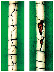
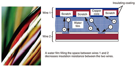
1. IntroductionThe insulation of electrical wires in aerial communication cables can fail when the insulating coating of the wire deteriorates and the inner copper core is exposed to the outside air through changes in the amount of rainfall or humidity. Addressing telecommunication failures associated with such insulation faults in aerial electrical cables requires a large number of work hours to search for and repair a faulty point; therefore, in terms of not only maintaining quality of telecommunication services but also reducing work hours, it is important to implement preventive measures against the cables being affected by changes in the amount of rainfall and humidity. This article presents two preventive measures for insulation faults in aerial electrical cables verified in an actual facility environment. 2. Mechanism of insulation faultsThe mechanism of insulation faults in aerial electrical cables involves the following steps: (1) The insulating coating of an electrical wire deteriorates through oxidation by oxygen in the air. (2) This deterioration is accelerated by factors such as heat, ultraviolet light, and sea salt. (3) Continuous cracks develop in the coating of the wire. (4) Moisture (condensation or rainwater) deposits on the exposed copper core. (5) Insulation resistance of the wire decreases, and the insulation fails. The coating of an electrical wire inside a closure mainly deteriorates due to oxygen, heat, etc. and exposes the copper core inside the wire (Fig. 1). Moisture adheres to the exposed copper core and forms a water film, which lowers the insulation resistance between the wires (Fig. 2). If the insulation resistance falls below a certain threshold, i.e., insulation fault occurs, the quality of telecommunications degrades.
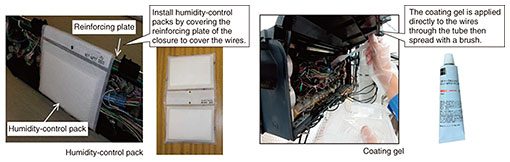
3. Overview of preventive measuresHumidity-control packs and coating gels are currently used by NTT EAST and NTT WEST as preventive measures against moisture (e.g., condensation) in closures caused by rainfall and humidity (Fig. 3).
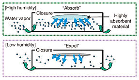
The humidity-control pack is composed of highly absorbent polymer particles that can absorb moisture in a high-humidity environment and expel it in a low-humidity environment, keeping the humidity constant and prevent condensation by absorbing and expelling the moisture inside the semi-sealed closure (Fig. 4).
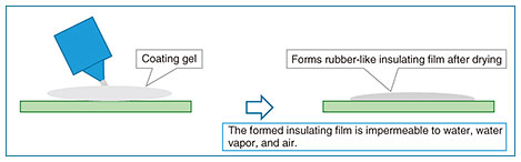
The coating gel is a coating material with excellent water resistance and electrical insulation. When applied to wires, the gel forms a rubber-like film after drying, which is expected to prevent exposed copper cores from coming into contact with adherent moisture and neighboring wires (Fig. 5).
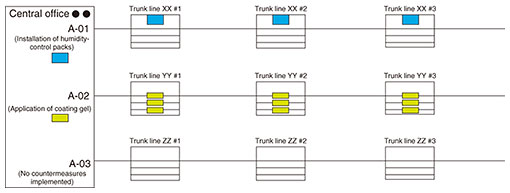
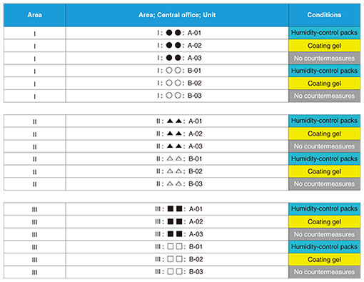
4. Details of field trial4.1 Trial areaWe sampled areas with high failure rates of aerial electrical cables throughout the year and a significant increase in failure rates from July to September (a period of high humidity and rainfall in Japan) and selected three areas from those samples. 4.2 ConfigurationTo compare the effects of the preventive measures (humidity-control packs and coating gel) under the same environment in each of the three areas, we prepared three configurations, i.e., installation of humidity-control packs, application of coating gel, and no countermeasures implemented, for units*1 connected to the same central office in each area (Fig. 6). We selected two central offices per area and three units per central office (18 units in total) with relatively high failure rate and assigned the unit to each of the above three configurations at each central office (Fig. 7).
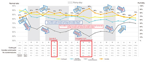
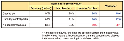
The two preventive measures were applied to all the closures connected to each unit to confirm their effectiveness of these measures. 4.3 Analysis methodInsulation-resistance tests of all the verification wires in the 18 units were first conducted in February, before the implementation of the two preventive measures (referred to as February (before)), and in March, after the preventive measures (referred to as March (after)), when rainfall is sparse. To observe fluctuations in insulation resistance, the insulation resistance tests were then conducted daily at certain times during a five-month period (June 5 to October 16) when rainfall was plentiful. We focused on the ratio of the number of normal wires to the total number of verification wires (referred to as normal ratio) and investigated two points: (i) whether the normal ratio correlated with changes in the amount of rainfall and humidity and (ii) whether the preventive measures could mitigate the impact of changes in the amount of rainfall and humidity on the normal ratio. 4.4 Trial resultsIn all three areas, the normal ratio of the units without preventive measures being implemented (without preventive measure units) was unstable and decreased significantly during increases in rainfall and humidity. For units with implemented preventive measures (with preventive measure units), however, the decrease in the normal ratio was small and stable (Fig. 8). Note that after September 19, for without preventive measure units, the normal ratio recovered to almost the same level as those from the February (before) and March (after) tests (Fig. 8).
5. DiscussionSince the normal ratio of both with and without preventive measure units decreases during heavy rainfall and high humidity, and that of without preventive measure units recovered as the amount of rainfall and humidity decreased after September 19, we consider that there is a correlation between the normal ratio and amount of rainfall and humidity. From a viewpoint of the effectiveness of these preventive measures for mitigating the impact of changes in the amount of rainfall and humidity, we confirmed the normal ratio of with preventive measure units remained stable throughout the trial period (June 5 to October 16) (Fig. 9). This finding suggests that telecommunication failure caused by insulation faults due to condensation under high-humidity conditions can be suppressed by implementing these preventive measures.
6. ConclusionThe effectiveness of two preventive measures against insulation faults in aerial electrical cables was verified in an actual facility environment. The insulation resistance of without preventive measure units varies greatly during periods of high humidity and heavy rainfall and other periods; in contrast, that of with preventive measure units stayed fairly stable throughout the year. Since aerial electrical cables are deployed with multiple wire connections*2, installing humidity-control packs and applying coating gel to only some of the closures may not prevent insulation faults occurring in the unit. As confirmed from the results of this field trial, these preventive measures should be applied to all closures in the target units to increase the effectiveness of the measures. The Access Network Engineering Group of Technical Assistance and Support Center, NTT EAST provides technical support to resolve difficult-to-solve failures of access network equipment and facilities that occur throughout Japan. We will continue to contribute to resolving problems in the field and develop tools for improving technical capabilities and efficiency by using the expertise gained through technical support and knowledge gained through the investigation of the causes of failures.
|
||||||